
No Job is Too Big or Too Small!
2026 Top Circuit Board Material Types for Global Buyers
Choosing a Circuit Board Material is no longer a simple exercise in comparing price per sheet. Global buyers must connect material data with real operating conditions, production capability, and supply continuity.
A high-speed server board may need low Dk and low Df laminates. An automotive controller may demand strong thermal cycling performance. A compact HDI design can expose weaknesses in resin flow, glass-weave effects, or via reliability. Copper foil, dielectric thickness, Tg, CTE, moisture absorption, and CAF resistance all deserve practical review. The numbers matter. The manufacturing process matters more than many buyers expect.
John D. Coonrod, a respected Rogers Corporation materials expert, has described material selection as “a compromise between electrical, thermal, mechanical, and cost requirements.” That sentence remains useful for purchasing teams in 2026. No single Circuit Board Material solves every design problem. A low-loss laminate may increase fabrication cost. A halogen-free option may require adjusted pressing conditions. A high-Tg material may still perform poorly when moisture control is neglected.
This guide examines the leading material types for global buyers, including FR-4, high-Tg laminates, halogen-free systems, PTFE-based materials, polyimide, metal-core boards, and flexible substrates. It considers signal integrity, heat dissipation, durability, certification expectations, and regional availability.
Some comparisons will remain imperfect. Supplier data is not always presented consistently. Laboratory results may not predict every factory outcome. Buyers should request current datasheets, stack-up guidance, test reports, and sample builds before approving volume orders. A cheaper sheet can become expensive after rework, delays, or field failures.
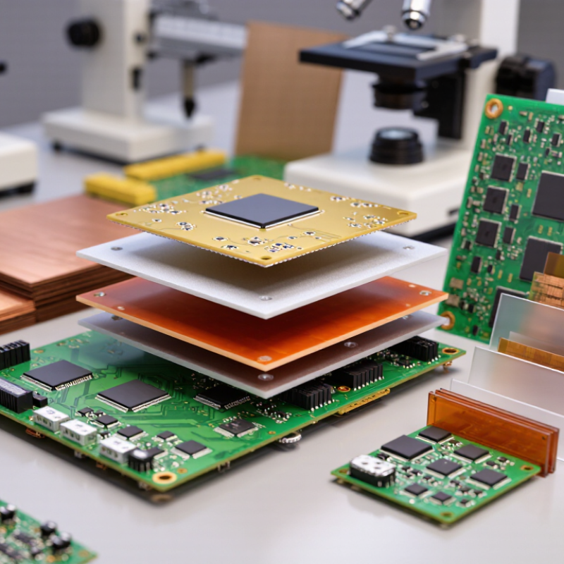
Classify PCB Materials Under IPC-4101: FR-4, PTFE, CEM, and Metal-Core
2026 Top Circuit Board Material Types for Global Buyers
IPC-4101 classifies PCB base materials by electrical, thermal, mechanical, and flammability performance. FR-4 remains the general-purpose choice because woven glass reinforcement supports stable drilling and dimensional control. Standard FR-4 typically uses epoxy resin with a glass transition temperature around 130–180°C, depending on the grade. It suits control boards, industrial modules, and many power-conversion assemblies.
PTFE materials target high-frequency designs. Their low dielectric loss helps preserve signal integrity at microwave and radar frequencies. However, PTFE can deform during drilling and needs tighter process control. CEM materials combine paper or glass reinforcement with epoxy resin. They can reduce cost in simpler consumer and appliance boards, but their thermal and mechanical margins may be narrower than FR-4. Not every board needs PTFE.
Metal-core materials use an aluminum or copper base to move heat away from LEDs and power components. The U.S. Geological Survey’s 2024 Mineral Commodity Summaries reported about 22 million metric tons of mined copper production in 2023, showing the scale behind copper-intensive supply chains. Still, raw material availability does not guarantee stable pricing. IPC’s 2024 industry outlook also continued to emphasize capacity, lead-time, and regional sourcing risks. A practical mistake is choosing materials from the schematic alone. Engineers should verify dielectric thickness, thermal resistance, copper weight, operating temperature, and IPC-4101 compliance with the fabricator. The classification is useful, but not perfect.
| Material Family | IPC-4101 Classification / Specification Basis | Typical Construction | Typical Tg or Thermal Characteristic | Typical Dk Range | Typical Dissipation Factor | Thermal Conductivity | Common PCB Uses | Key Buying and Design Checks |
|---|---|---|---|---|---|---|---|---|
| Standard FR-4 Epoxy | FR-4 family Flame-retardant glass-reinforced epoxy laminate. Confirm the supplier’s applicable IPC-4101 slash-sheet designation and qualification data. | Woven E-glass reinforcement impregnated with epoxy resin; copper-clad sheets are available in multiple glass styles and resin contents. | Typically 130–170 °C Tg. Common lead-free assembly capability when the selected grade and process are qualified. | Approximately 4.0–4.8 at 1 GHz; construction-dependent. | Approximately 0.009–0.020 at 1 GHz; frequency- and resin-dependent. | Approximately 0.25–0.40 W/m·K through the dielectric. | General multilayer boards, industrial controls, consumer electronics, computers, communication equipment, and many automotive control assemblies. | Specify Tg, Td, CTE, Z-axis expansion, copper foil type, glass style, dielectric thickness tolerance, flammability rating, and CAF performance where relevant. |
| High-Tg FR-4 Epoxy | FR-4 high-temperature family Higher-temperature FR-4 construction qualified against the applicable IPC-4101 material requirements. | Woven E-glass with modified epoxy resin systems designed for improved thermal stability and multilayer reliability. | Typically 170–200 °C Tg. Often selected for repeated lead-free reflow, higher operating temperatures, or improved dimensional stability. | Approximately 4.1–4.7 at 1 GHz. | Approximately 0.010–0.020 at 1 GHz. | Approximately 0.25–0.45 W/m·K through the dielectric. | High-layer-count boards, power control, industrial equipment, automotive electronics, telecom hardware, and products exposed to thermal cycling. | Do not select by Tg alone; review Td, T260/T288 time, Z-axis CTE, resin content, drilling behavior, press-cycle compatibility, and actual reflow profile. |
| Low-Loss or High-Speed FR-4 | FR-4 performance-enhanced family IPC-4101-compliant material selection should be confirmed together with the electrical test method and controlled-impedance requirements. | Glass-reinforced epoxy or modified epoxy with lower-loss resin chemistry, controlled resin content, and carefully selected glass styles. | Commonly 150–200 °C Tg, depending on grade. Thermal values must be reviewed together with signal-integrity data. | Approximately 3.3–4.2 at 1–10 GHz; laminate-specific. | Approximately 0.004–0.012 at 1–10 GHz; test-method-dependent. | Approximately 0.25–0.50 W/m·K through the dielectric. | High-speed digital backplanes, networking equipment, servers, storage systems, RF control sections, and high-frequency digital interconnects. | Request Dk/Df data at the target frequency, test method, resin content, glass weave information, impedance tolerance, skew-control capability, and lot-to-lot consistency. |
| PTFE-Based RF Laminate | PTFE / RF family PTFE-based copper-clad materials are selected under the applicable IPC-4101 RF-material requirements and the supplier’s qualification documentation. | PTFE resin with woven glass, ceramic filler, or a hybrid reinforcement system; available in low-loss and low-Dk constructions. | PTFE melting point is approximately 327 °C; a conventional epoxy-style Tg is generally not the primary selection parameter. | Approximately 2.1–3.5 at 10 GHz, depending on filler and reinforcement. | Approximately 0.0009–0.0035 at 10 GHz for low-loss constructions. | Approximately 0.20–0.80 W/m·K, depending on ceramic loading and construction. | Microwave circuits, antennas, radar, satellite communications, RF filters, power amplifiers, and other low-loss transmission-line applications. | Check Dk uniformity, Df at the operating frequency, dimensional stability, copper roughness, drill and plating process, lamination method, coefficient of thermal expansion, and moisture behavior. |
| CEM-1 | CEM-1 family Composite epoxy material with paper-based core and glass-fiber surface layers; verify the applicable IPC-4101 material specification and flammability requirements. | Cellulose-paper core impregnated with epoxy resin, normally covered with woven glass-fiber layers and copper foil. | Typically 110–130 °C Tg. Generally less suitable than FR-4 for demanding multilayer and repeated high-temperature assembly. | Approximately 4.2–5.2 at 1 MHz to 1 GHz; construction-dependent. | Approximately 0.015–0.025 at 1 MHz to 1 GHz. | Approximately 0.20–0.35 W/m·K through the dielectric. | Cost-sensitive single-sided or simple double-sided boards, household appliances, lighting controls, and low-to-moderate complexity products. | Confirm multilayer suitability, hole-wall reliability, dimensional tolerance, moisture resistance, flammability rating, punching or routing process, and assembly temperature limits. |
| CEM-3 | CEM-3 family Composite epoxy material using glass-fiber nonwoven core construction; confirm the exact IPC-4101 specification basis before procurement. | Nonwoven glass-fiber core impregnated with epoxy resin, commonly combined with woven glass-fiber surface layers and copper foil. | Typically 110–140 °C Tg. Better mechanical processing consistency than paper-core composites in many applications. | Approximately 4.0–5.0 at 1 MHz to 1 GHz. | Approximately 0.012–0.020 at 1 MHz to 1 GHz. | Approximately 0.20–0.40 W/m·K through the dielectric. | High-volume double-sided boards, consumer products, appliance controls, lighting equipment, and moderately complex electronic assemblies. | Review press-fit and plated-through-hole requirements, dimensional stability, resin content, copper adhesion, thermal endurance, and compatibility with lead-free soldering. |
| Aluminum Metal-Core PCB | Metal-core / metal-clad construction Specify the applicable IPC-4101 dielectric material requirements together with metal-core construction, thermal performance, and electrical insulation requirements. | Copper circuit layer, electrically insulating dielectric layer, and aluminum heat-spreader base. One-layer and multilayer versions are available. | No single Tg defines the complete assembly; dielectric Tg is commonly about 120–170 °C. Aluminum base typically melts near 660 °C. | Dielectric Dk typically approximately 3.2–4.5; construction-dependent. | Dielectric Df typically approximately 0.008–0.025. | Dielectric layer typically 1–8 W/m·K; aluminum base approximately 150–220 W/m·K. | LED lighting, power converters, motor drives, automotive power electronics, battery systems, and applications requiring heat spreading. | Specify dielectric thermal conductivity, dielectric thickness, breakdown voltage, thermal resistance, metal thickness, flatness, insulation edge clearance, and thermal-interface design. |
| Copper Metal-Core PCB | Metal-core / metal-clad construction Confirm the applicable IPC-4101 dielectric requirements and the metal-core thermal, electrical, and mechanical acceptance criteria. | Copper circuit layer, electrically insulating dielectric layer, and copper heat-spreader base; selected where very high heat spreading or low electrical resistance is required. | Dielectric Tg commonly about 120–170 °C. Copper melts near 1,085 °C; operating limits are governed by the dielectric and complete assembly. | Dielectric Dk typically approximately 3.2–4.5. | Dielectric Df typically approximately 0.008–0.025. | Dielectric layer typically 1–8 W/m·K; copper base approximately 300–400 W/m·K. | High-power LED modules, high-current power electronics, traction systems, thermal spreaders, and demanding industrial power assemblies. | Evaluate weight, cost, coefficient of thermal expansion, dielectric breakdown, galvanic compatibility, machining, solder-joint stress, and the board-to-heatsink interface. |